How to configure Frame Relay in Cisco Networking Devices (Eg. 2)
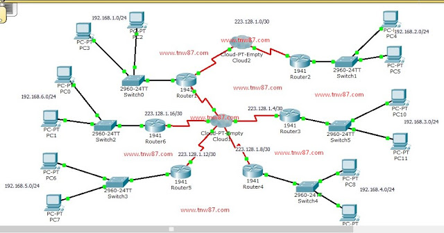
The example of how to configure the Frame Relay in Cisco Networking Devices is shown in the below with the picture together. I hope this example will be benefit for brothers and sisters who are learning Cisco Networking.
Router 1
en
config t
hostname R1
int g0/0
ip address 192.168.1.1 255.255.255.0
no shut
int s0/0/0
description Link From Router1 to Router2
ip address 223.128.1.1 255.255.255.252
encap frame-relay
frame-relay lmi-type cisco
frame-relay interface-dlci 101
no shut
int s0/0/1
encap frame-relay
no shut
exit
int s0/0/1.201 point-to-point
description Link From R1 to R3
ip address 223.128.1.5 255.255.255.252
frame-relay interface-dlci 201
no shut
exit
int s0/0/1.301 point-to-point
description Link From R1 to R4
ip address 223.128.1.9 255.255.255.252
frame-relay interface-dlci 301
no shut
exit
int s0/0/1.401 point-to-point
description Link From R1 to R5
ip address 223.128.1.13 255.255.255.252
frame-relay interface-dlci 401
no shut
exit
int s0/0/1.501 point-to-point
description Link From R1 to R6
ip address 223.128.1.17 255.255.255.252
frame-relay interface-dlci 501
no shut
exit
router rip
version 2
network 192.168.1.0
network 223.128.1.0
network 223.128.1.4
network 223.128.1.8
network 223.128.1.12
network 223.128.1.16
end
copy run start
Router 2
en
config t
hostname R1
int g0/0
ip address 192.168.2.1 255.255.255.0
no shut
int s0/0/0
description Router2 to Router1
ip address 223.128.1.2 255.255.255.252
encap frame-relay
frame-relay lmi-type cisco
frame-relay interface-dlci 102
no shut
exit
router rip
version 2
network 192.168.2.0
network 223.128.1.0
end
copy run start
Router 3
en
config t
hostname R3
int g0/0
description Link From Router3 to Router1
ip address 192.168.3.1 255.255.255.0
no shut
int s0/1/0
description Link From Router3 to Router1
ip address 223.128.1.6 255.255.255.252
encap frame-relay
frame-relay lmi-type cisco
frame-relay interface-dlci 103
no shut
exit
router rip
version 2
network 192.168.3.0
network 223.128.1.4
end
copy run start
Router 4
en
config t
hostname R4
int g0/0
ip address 192.168.4.1 255.255.255.0
no shut
int s0/1/0
description Link From R4 to R1
ip address 223.128.1.10 255.255.255.252
encap frame-relay
frame-relay lmi-type cisco
frame-relay interface-dlci 104
no shut
exit
router rip
version 2
network 192.168.4.0
network 223.128.1.8
end
copy run start
Router 5
en
config t
hostname R5
int g0/0
ip address 192.168.5.1 255.255.255.0
no shut
int s0/0/0
description Link From Router5 to Router1
ip address 223.128.1.14 255.255.255.252
encap frame-relay
frame-relay lmi-type cisco
frame-relay interface-dlci 105
no shut
exit
router rip
version 2
network 192.168.5.0
network 223.128.1.12
end
copy run start
Router 6
en
config t
hostname R6
int g0/0
ip address 192.168.6.1 255.255.255.0
no shut
int s0/1/0
description Link From Router6 to Router1
ip address 223.128.1.18 255.255.255.252
encap frame-relay
frame-relay lmi-type cisco
frame-relay interface-dlci 106
no shut
exit
router rip
version 2
network 192.168.6.0
network 223.128.1.16
end
copy run start
***Thank You***